
The rapid development of China's auto industry has put forward higher requirements for the quality and manufacturing cycle of car cover moulds. The traditional mold manufacturing methods can no longer meet the market demand. The current development direction of mold manufacturing technology is: the computer application in the early stage gradually replaces the on-site operation, and the high-precision processing gradually replaces the manual manual debugging. The mold design and manufacturing are highly standardized, and the single-piece production method is developed to the production line.
The traditional stamping process design adopts DL diagram, the focus is on formability, and the die face processing is relatively extensive. Numerical control programming and numerical control machining generally use digital die face to directly perform numerical control programming, and the upper and lower die faces adopt equal gap processing mode. The advantages of 3D modeling technology and high-precision, high-speed CNC machining technology are not fully utilized. The die face design of this manufacturing method is actually realized by post-production and debugging, resulting in a large amount of research and distribution in the later stage, and more rework and rework of CNC machining. Invalidity and repetitive processing. How to ease the pressure of the two mold bottleneck processes of CNC machining, research and debugging, and thus shorten the entire mold manufacturing cycle has become an urgent problem for the domestic mold industry. The foreign leading mold industry already has mature and refined die face design technology. Through the pre-fine digital model technology, the initial quality of the part T001 is improved, the mold fitting time is shortened, the commissioning cycle is shortened, the commissioning cost is shortened, and the component pass rate is quickly improved. . Its die face design and commissioning process has truly formed a closed loop manufacturing system.
The development of fine mold surface technology, the development of refined mold surface design process, integrated into the mold manufacturing process, the specific main technical indicators are as follows: 1 for large-scale cover mold under heavy load bending deformation, using digital mold overall deformation modeling technology It is supplemented to replace the traditional pad angle machining compensation to improve the compensation accuracy and improve efficiency. 2 Solve the technical problem of convex and concave die fill interference caused by machining residue. 3 Improve the success rate of the first test mode, improve the initial quality of T001, save 15% to 20% of the press machine, and shorten the mold debugging cycle by 30%. 4 Through the design of the clearance surface, the CNC machining efficiency of the machine tool is improved, and the CNC milling machine table is reduced by 10%.
1. Fine work surface technology workflow points
(1) Work in the design phase. In view of the fact that the mold is being tested and the commissioning cycle is generally long, the design stage is modified for the conventional thick material gap surface mold surface, and the gap between the upper and lower molds is changed by changing the overall shape and local shape of the mold surface. To achieve the purpose of shortening the training and debugging cycle.
Make full use of the CAE analysis results and the experience accumulated in the mold research and debugging process, and develop the corresponding mold surface pre-compensation module for the common problems.
(2) The work of CNC programming and processing stage. The workload of clearing roots, secondary empty knives, grinding, pressing, and non-working area surface opening in the manufacturing process is moved forward to the NC programming/die surface modeling stage to reduce the pressure on the bottleneck process such as CNC machining and clamp adjustment. This enables greater capacity to be invested in the quality improvement of stampings, which in turn shortens manufacturing cycles and improves mold quality.
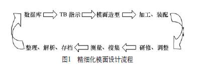
(3) Optimization of mold manufacturing process: stamping process design → TB indication → die surface modeling → CNC programming → CNC machining → research and debugging, debugging, forming a benign closed loop (see Figure 1). Establish analytical positions, create gap indication maps, and indicate die face design: including the actual contour surface area of ​​the mold, the gap value of each shape area, the mold surface change of the process requirements, the variation of the draw fillet, and the various mold faces. Knockout, deflection compensation instructions and reserved compensation instructions.
To establish the mold surface modeling position, the initial technicians complete the refined mold surface design according to the gap indication; after the various standards and specifications are perfected, the general clearance standard of the typical parts is established, and the analysts only need to make individual gap indications for the parts characteristics. The personnel complete the die face design according to the priority order of the individual gap indication and the general gap indication. At the same time, the problems accumulated in the actual mold-distribution and debugging process are collated, analyzed and archived, and the surface of the mold after the grinding is measured by the digital detection technology of the three-dimensional photogrammetry, and compared with the design surface, the mold surface correction is established or corrected. Data, gradually form a knowledge base of die face compensation for typical parts to guide the next fine face design.
2. Development and application of reserved modeling technology
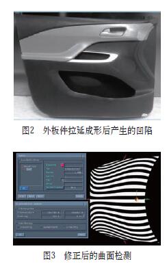
The local profile depression of the outer panel is a common problem of all outer panels: the overall deformation exists in parts with poor strength such as the top cover and the outer trunk of the luggage; the large deformation position exists in the part where the shape is suddenly changed, such as the door handle periphery. , the side of the B-pillar up and down, around the luggage license plate lights and other parts (see Figure 2). The depressions in these areas are inevitable, and it is also the longest and most energy-intensive part of the outer panel mold research and quality improvement.
The traditional method is to reduce the degree of depression by the strong pressure of the die, and continuously adjust it by repeated field observation and analysis. However, the die pressure has a poor effect, a large amount of work and a large number of adjustment rounds. The shape compensation technology reserved for the concave compensation can effectively solve the problems existing in traditional production. The difficulty of this technology is as follows.
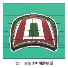
(1) Correction of Class A surfaces. Since the area where the depression occurs generally involves the A-level surface, the shape of the A-level surface is maintained while ensuring the accuracy of the mold surface compensation. To this end, we have established the correction and evaluation criteria for the A-level surface, and the contrast analysis of the surface before and after the deformation, including the shadow detection, the highlight detection, and the curvature detection of the section line, and the correction of the morphological change area (see Figure 3).
In addition to the collapse of the outer panel, the common resilience trend of some parts is also a traditional difficult problem that affects the improvement of the mold quality, such as the torsion of the hinge part of the door panel, the sinking of the side cover part and the cover hood. Flattening of the flanging, etc., the general dimensional deviation varies from a few millimeters to a dozen millimeters, and it is sometimes necessary to use several rounds to complete the correction through the on-site field measurement. Therefore, the depression and rebound of each part are summarized. Regularity and establishment of typical parts reserve compensation standards, through the initial active reservation can effectively reduce the amount of mold rework work in the late stage.
(2) Application of gap modeling technology. The die face is divided into a strong nip zone, a vacant zone and a base zone, and smooth transitions are maintained between the zones. The high-precision, high-speed NC machining is used to realize the processing of microscopic unequal gap die faces, and the NC machining of different parts of the die is reasonably controlled. Accuracy, which not only effectively reduces the mold research and adjustment work hours, improves the quality of the parts, but also improves the processing efficiency and effect of the numerical control equipment, effectively shortening the mold making cycle.
Design of the strong nip area: The strong nip area, that is, the gap between the upper and lower die faces is smaller than the thickness of the sheet material, and the value is generally -0.15 to -0.05 mm, depending on the position of the strong pressure. By reducing the gap to control the flow of the sheet material, the dimensional accuracy of the strong pressure region is ensured, and surface defects such as wrinkles are eliminated.
Design of the open area: Increase the gap between the upper and lower die faces in a specific area, mainly to reduce the fit of the fitter, eliminate the influence of machining residues, and improve the efficiency of CNC machining through the control of machining accuracy in different areas. To shorten the CNC machining man-hour, the open value is determined according to the specific position.
Modeling of the gap area: The CAD area (UG/ThinkDesign) is used to cut and divide the surface of the strong nip and the open area, and to offset or translate the corresponding size and direction. The special area should adopt the method of offset + translation. Smooth connections are made between the various areas by bridging or matching. For the outer surface, the transition area should be large enough to avoid surface defects caused by drastic changes.
The die face after the gap modeling is shown in Fig. 4. 1 Strong nip position and color mark indicate red. 2 Transition zone: The tangent surface of the gap surface and the non-gap surface bridge is generally 5-20 mm. If the position is not enough, the adjacent two surface transition zones are made in the gap area. 3 The gap of the pressure ring is 0.1mm, the concave mold is enlarged without gap value; the other areas of the pressure ring are digitally simulated. 4 The color boundary line is not marked according to the actual mark. If the local open area is too small and difficult to process, it may not be done. The 5 concave R portion is 30% smaller than the digital standard R value.
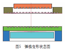
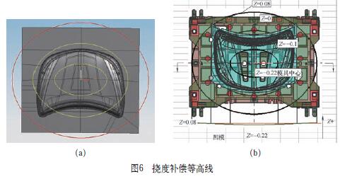
(3) Development and application of deflection modeling technology. With the continuous development of processing technology, the mold has been generally used high-speed high-precision numerical control equipment for profile processing, and its processing accuracy has reached less than 5μm. However, when the large-size cover mold processed by the precision numerical control equipment is clamped, there is still a large area of ​​interference, and the amount of repair is 0.3 to 0.5 mm. The mechanical deformation of the mechanical press is shown in Figure 5.
Determine the deformation center line of the mold according to the deflection profile (0 line), calculate the deformation value of the center point of the concave mold, calculate the deflection deformation contour line; calculate the deformation value of the center point of the pressure ring according to the deflection distribution map, and calculate the deflection deformation contour line (see Image 6).
3. CNC machining rounding avoidance technology
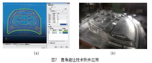
Through the development and application of gap modeling and deflection modeling technology, the research and development rate of the drawing die has been greatly improved. However, in the process of drawing and assembling large-sized cover members, a large number of interference parts are still found, and the main parts are concentrated in the upper and lower parts. Between the convex and concave fillets of the mold, the main reason for the detection is the processing residue caused by the small-diameter concave fillet in the clear angle processing, resulting in interference caused by the reduction of the gap. The radius of curvature of the concave surface of the die face is reduced, and the corresponding convex fillet of the die face remains unchanged, thereby increasing the gap between the rounded portions between the upper and lower molds, thereby compensating for the problem of machining residual of the small diameter tool. According to the radius of curvature, the radius of curvature is reduced by 0.5~2mm, and the continuity between adjacent surfaces is guaranteed. The rounded avoidance technology software application is shown in Figure 7.
4. Conclusion
After several years of application, the refined die face design technology has achieved great results, greatly improved the success rate of the first test mode, improved the quality of the first press, shortened the mold development and debugging cycle, and reduced the pressure of resource scarcity. When the machine and CNC machine tools are used, the pressure of the “bottleneck†process that is common in the mold industry has been greatly alleviated, which has brought significant economic benefits to the company, mainly reflected in: greatly improving the efficiency of CNC machining and shortening the time of CNC machining. Reduce the frequency of rework and rework of CNC machining, reduce the repetitive and inefficient processing; reduce the tool cost; greatly shorten the training and debugging cycle, reduce the occupation of the single set of die presses, improve the quality of parts, and reduce the post-debugging rounds. .
Compared with the international cutting-edge mold enterprises, the current fine-grained die-face design in China is close to the advanced foreign technology level, but due to the late start and poor professionalism, the feedback, collection, collation and re-integration of the on-site debugging data are applied again. There is still a certain gap. It is believed that with the accumulation of experience, the gap with leading foreign technology will be gradually reduced, and a virtuous circle will be formed.
Stainless Steel Pipe Fitting, Brass Pipe Fitting, Elbow Pipe Fitting, Water Pipe Fitting
ZHEJIANG KINGSIR VALVE CO., LTD. , https://www.kingsirvalves.com