In recent years, with the rapid development of China's water conservancy, shipbuilding, power generation, mining, locomotive and other large and heavy enterprises, the supporting problems of important large-scale components have become more prominent.
To a certain extent, these large parts rely on imports for blanks and processing, which limits the development of the industry. Therefore, there is an urgent need to develop some equipment suitable for processing such parts.
The processing of this type of parts has the common points: the slender shaft of the parts, the weight, the number of processes, and the long working hours. The domestic use of multiple tools and multiple equipments is done in sequence; there are also imported milling and milling in the finishing process. Completed by the center. The overall performance is low and is subject to high prices of imported equipment.
The development and application of machine tools for foreign horizontal milling and milling machining centers is relatively early, and the technology is relatively mature, such as WFL in Austria and Nielsen in Germany. The turning and milling center is equipped with a single tool holder. The rotating tool and the turning tool are installed at the same position. The power shaft is extended and the rigidity is low.
The following is a series of horizontal turning and milling combined machining centers developed in recent years for the processing of important large-scale long-axis parts required by large and heavy enterprises.
Analysis of processing technology of large parts
Typical part
Take the marine crankshaft of the shipbuilding industry as an example (see Figure 1): the material is mostly cast iron or forged steel, and the remaining amount of the blank is as high as 20~30mm, and it is uneven and high in hardness. The shape is a long shaft with multiple cranks. Since the rotary shaft of the crank, that is, the connecting rod neck and the main journal, are different, the crank has a large diameter around the main journal, and the crank contour is composed of a plurality of different arcs, and both ends of the crankshaft are very The deep oil hole, the angularly inclined oil hole on the crank, and the like, are required to be completed by a large-sized compound turning and milling machining center which is high in rigidity and suitable for rough finishing.
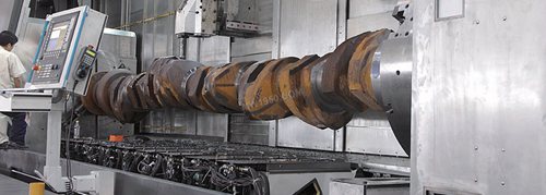
figure 1
2. The front crankshaft machining process is not used in the horizontal turning and milling combined machining center
The processing plan of a diesel engine manufacturer is mainly completed by multiple processes and multiple equipments: First, the center hole is used to punch the center hole, and the flat end face is moved; then the processed parts are moved to the special double-spindle box lathe, the coarse and fine car main neck And the outer side of the crank; then adjust the special fixture on the two headstocks, move the connecting rod neck to the turning diameter of the machine tool spindle, perform workpiece positioning, alignment and clamping, and rough and fine the connecting rod neck and the inner side of the crank Processing, and then on the floor milling machine thick, fine balance heavy surface; finally the workpiece on the drill bed to complete the oblique oil hole, straight oil hole and deep hole processing. This kind of machining scheme is completed on the ordinary sleeping car, the efficiency is low, and the adjustment is time-consuming. When the stroke of the workpiece is large, the fixture can not meet the processing demand, and the multi-process also affects the machining precision of the workpiece.
3. Adopting imported horizontal turning and milling machining center crankshaft processing technology
With the development of China's shipbuilding industry, the quality of the crankshaft is increasingly in line with international standards. In recent years, leading companies in this industry have begun to introduce turning and milling composite machining centers such as WFL in Austria and Nielsen in Germany. Considering the cutting performance of this type of machine tool, the equipment is used for the semi-finishing and finishing processes of the crankshaft, and the machining of the parts from the blank to the grinding can not be realized once.
With the increasing demand for medium and low speed diesel engines and the discussion of foreign crankshaft processing technology, machine tool manufacturers have developed a large horizontal milling and milling machining center with independent property rights.
Large horizontal turning and milling combined machining center technology
Overall layout
The machine tool is shown in Figure 2. Generally, the slant bed, the double-spindle box, the side-mounted single column, and the double-sided hanging box are provided with a double tool holder structure, and the cutter is placed in the direction of gravity, with workpiece detection, tool detection, tool magazine, constant temperature cooling device. , water cooling device, chip removal device, protective device and electrical device, etc., and using Siemens 840D sl CNC system (see Figure 3).
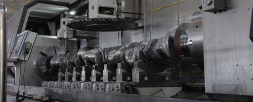
figure 2
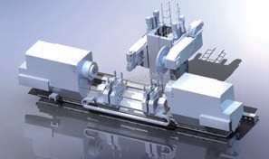
image 3
The device has (X 1 , X 2 , Y 1 , Y2 , Z1 , Z2 , B1 , B2 , Cf1 , Cf2 ) any 5-axis linkage function , dual spindle , dual Cf axis synchronization function , center frame and sub spindle can be respectively along Z Automatic movement function in the axis direction, turning and milling combined machining function, using the heavy-duty tool to cut the deep hole function, high-pressure internal cooling function, on-machine detection function and on-line real-time monitoring function of the tool.
A set of side hanging boxes is arranged on the left and right sides of the single column, and the tool holder is arranged thereon. The left tool holder has a B-axis function, and the right tool holder is equipped with a large-diameter outer milling cutter plate for roughing and roughing.
The built-in 52kW internal motor and a two-stage planetary gearbox are integrated inside the left-hand hanging box, which is compact. The built-in motor and reducer are installed in the multi-step deep hole box formed by the potting process. The development process solves the problem of low precision of multi-step deep hole machining. The output torque of this device is better than that of imported machine tools.
The 78kW spindle motor on the right side of the box is decelerated by the toothed belt and the self-made gearbox to provide 10 000 N·m of large torque power.
The gearbox can realize two-speed shifting. According to the different needs of users, the outer milling cutters of different diameters can be arranged to solve the problem that the tool length and rigidity are insufficient and rough machining cannot be realized.
2. Technical parameters are compared with foreign machine tools of the same specification
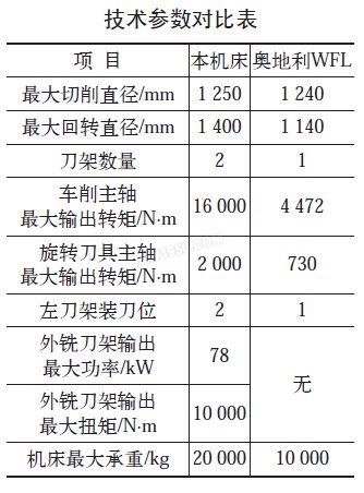
As can be seen from the attached table, the machine has obvious advantages in terms of load capacity, power and torque output, breaking the layout form of the existing single milling machine with only the single tool holder. The large-diameter cutter head of the right tool holder can realize the rough and fine machining of the workpiece on one machine tool, thus achieving high precision and high efficiency. The left tool holder and the turning spindle C axis function combine to realize 5-axis linkage. The Austrian WFL machine is shown in Figure 4.
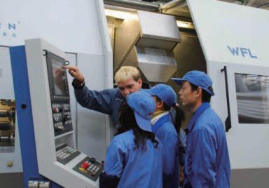
Figure 4
3. Technological innovation of equipment
(1) Single column technology. Although the machine is equipped with a double tool holder, it has a single column form for compact layout. The single column is hung on the inclined 30° bed and the ground auxiliary rail. Under the condition of ensuring the stability of the column movement, this layout can effectively reduce the weight of the machine and reduce the cost of raw materials and processing (see Figure 5).
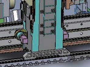
Figure 5
The single-column Z-direction (longitudinal) feed adopts a double-motor anti-backlash mechanism. When fast-feeding, the double-motor drive gear rotates in the same direction to meet the large starting torque required during starting; the double-motor drive gear rotates in reverse when the work enters, eliminating The transmission gap ensures that the single column runs smoothly and does not vibrate during the work (see Figure 6 and Figure 7).
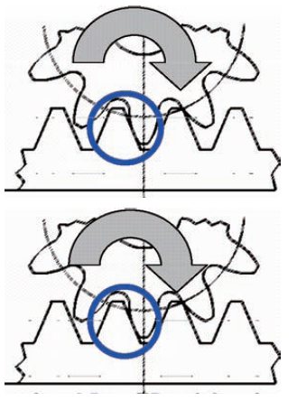
Image 6
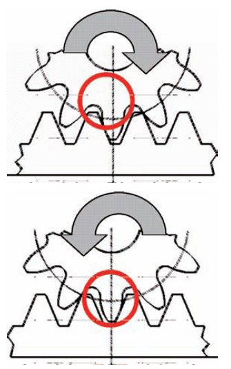
Figure 7
(2) Two-point cloth cutter technology for B-axis tool holder. The traditional turning and milling center is equipped with a single tool holder. The rotating tool and the turning tool are installed at the same position of the B-axis tool holder. A three-toothed disc mechanism for locking the turning tool must be provided. Therefore, the power shaft is extended and rigid. Low, not suitable for roughing; When machining medium and low speed crankshafts, due to the large diameter of the turning, the tool is bound to overhang, and it is impossible to finish rough finishing on one machine.
The equipment described in this paper, the front end of the left hanging box is equipped with a two-point knife B-axis tool holder (see Figure 8), which is equipped with rotary tool and turning tool mounting position respectively, reducing the turning tool on the power shaft. The locking gear plate mechanism increases the rigidity of the tool holder and enables rough finishing to be realized on two devices.
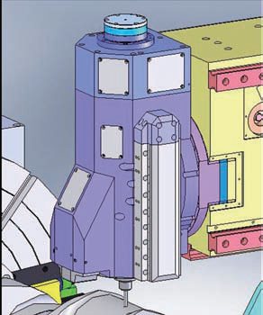
Figure 8
In the implementation of technological innovation: the air seal of the spindle bearing of the B-axis tool holder, the material selection of the B-axis arbitrary locking component, and the development of the 2-point tool change control program are all involved, and become the guarantee of rigidity and reliability superior to imported products.
(3) The left side hanging box (see Figure 9).
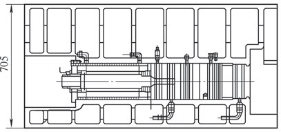
Figure 9
At present, the domestic large-scale turning and milling center side hanging box mostly adopts the structure of the power motor and the reducer externally, that is, the power motor and the speed reducer are installed at the top of the box, and are transmitted to the lower part of the box through the slender transmission shaft, and then transmitted to the front end knife. frame. The power motor and the reducer occupy a large space in this structure, and the power, the rotational speed and the torque of the output shaft cannot be designed too high due to the transmission of power through the elongated transmission shaft.
The equipment described in this paper, the spindle motor and the reducer are integrated in the left feed box. The structure is very compact. Due to the high connection precision of components such as spindle motor and reducer, the reliability and life of the components are effectively improved. At the same time, the shortening of the drive shaft can greatly improve the output power, torque and speed of the power shaft, thereby improving the components. Performance of the use. Due to the large size of the equipment, the inner holes for mounting these components are long and are solved by the potting process. The spindle motor is externally cooled by the cooling water of a separately circulated thermostatic cooling tank, which is lubricated and cooled by circulating cooling oil to ensure reliable structural performance.
The X-direction motion of the left-hand hanging box uses the dual-drive technology and the Y-direction motion to apply the suspension compensation technology to ensure the accuracy of the machine.
(4) Right tool holder for high torque output. In order to meet the rough machining requirements, the right tool holder with a torque of 10 000 N·m and a 1 400 mm diameter outer milling cutter can be installed. The right tool holder can be rotated or linearly moved along the Y axis. The right tool holder is locked on the right side of the hanging box by the toothed disc. After rotating, the cutter head has three postures. The cutter head faces the left and right for the machining position, and the cutter head faces the lower left frame for machining the right end of the workpiece. Stay on top of the right headstock. When the cutter head faces down, the small-diameter face milling cutter can also be replaced, and the linear motion along the Y-axis direction can be used for plane milling. The finite element analysis, the optimization of the three-toothed disc locking mechanism, and the high-strength and anti-vibration ductile iron of the tool holder housing ensure the realization of the function of the right tool post.
The right-handle large-diameter outer milling cutter head (see Fig. 10) solves the problem that when the rod milling cutter performs the milling of the connecting rod neck during the machining of the crankshaft workpiece in the imported machine tool, the tool overhang increases as the crankshaft diameter increases. The rigidity is insufficient, and roughing and inefficiency cannot be achieved.
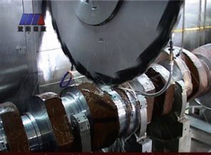
Figure 10
(5) The right side hanging box (see Figure 11). The 78kW power motor can provide an output torque of 10 000 N·m after being decelerated by the toothed belt and the self-made two-speed reduction gear box. According to the different needs of users, the milling cutter discs of different diameters can be arranged, for example, the diameter is 1 400 mm. The movement of the right side hanging box in the Y-axis direction is realized by the servo motor and the speed reducer mounted on the right side to drive the ball screw; when the fixed-point milling is performed, the Y-axis is locked by a plurality of cylinder pressure plates to avoid the force of the screw and ensure the machine tool The accuracy of the 550mm × 675mm large-section right-hand hanging box provides sufficient rigidity for the high-power output mechanism.
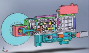
Figure 11
(6) Dovetail drag mechanism (see Figure 12). The equipment described in this article is primarily for the processing of elongated shaft parts. For parts with a length of 6m or more, 2 to 4 center frames may be required for machining to ensure machining accuracy. When the number of parts of a variety of parts is changed or the number of center frames used for a single type of parts is small, the relative distance between the center frames will change. If each center frame is equipped with a set of drive motors, the equipment cost will be high and the mechanism will be complicated. Easy to interfere.
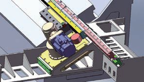
Figure 12
In view of the above situation, the equipment introduced in this paper adopts a special center frame dovetail drag mechanism: the power motor and reducer are fixed at the right end of the bed, and the dovetail rack with the jack up to 10m is driven on the dovetail rail fixed to the bed. Movement along the Z direction, with the latch mechanism and the detection switch on the center frame, the position of the center frame and the Z-direction are changed. The dovetail pair with a length of 10m and a cross-sectional area of ​​only 120mm×80mm is composed of 10 segments. The deformation of the docking interface in the loaded state is obtained by finite element analysis. It is pre-stretched through the adjustment pad in advance, avoiding the process of dragging the components. Jitter caused by elastic deformation. The process strictly controls the consistency of each piece of processing and performs measurements during installation. Each section of the dovetail guide is equipped with a lubrication unit to ensure smooth movement. Develop intelligent software, define the serial number of each jack on the dovetail rack, and the user only needs to input the part model to know the order of the dragged parts and the stroke amount. The dovetail drag mechanism technology is a brand-new design concept, cost-effective, and has obtained a practical new patent.
(7) Adaptive control technology. In the process of rough machining of 1 400mm outer milling cutter, such as crankshaft parts, due to the high hardness of the parts and the uneven margin, the constant cutting parameters are easy to cause the car or the knife. For this reason, adaptive control technology is applied: By detecting the load of the milling spindle, the internal expert load system is used to analyze the collected spindle load signal and the corresponding tool and workpiece material data, and the optimal feed rate of the machine tool is calculated in real time and applied to the milling process, thereby Amplitude increases production efficiency, and controls the feed rate in a stable, continuous, and automatic process during machining, while achieving dynamic tool and spindle protection.
In the process of processing, the adaptive control system can learn and re-learn according to the input and output data of the control object, continuously identify the model parameters and correct them.
As the production process continues, the model becomes more and more accurate, and finally adjusts itself to an optimal working state to optimize the machining process.
Conclusion
From the above discussion about the technology of large horizontal turning and milling composite machining center, it can be seen that the technical parameters and performance are both high in technical content and unique in innovation, which is worth promoting.
The devices described in this article now have several important customers. Its performance is an absolute leader in the domestic machine tool industry. Its successful trial production has broken the monopoly of large-scale and key equipment in key industries by foreign machine tools. It not only has the performance of well-known foreign brands, but also innovates and upgrades. It can completely replace imported machine tools to replace traditional crafts, and can make the processing of important parts of key national industries to a higher level. The machine tool also has a good cost performance, so it can save a lot of foreign exchange for the country, save a lot of money for the enterprise, bring considerable economic benefits, and the application prospect is very broad.
Single handle Basin Faucet is easy for our normal life. You can control water with one hand easily.
Different style , different materials and different finish can satisfied with all your requirement. Pls feel free to contact us for further information.
Single Handle Basin Faucet,Single Basin Faucet,Old Style Single Tap Basin Faucets,Single Hole Basin Faucet
Kecheng Trading Company Limited , https://www.jmttl.com
