
Different forms of isolation banks have different uses. The isolated embankment on the same side is mainly used to block the extension of the boundary line on the surface. The isolation levees at the corners are used to prevent the boundary line from expanding from one component to the other on the workpiece.
To obtain the effect of preventing the extension of the boundary line, there should be certain requirements for the width of the gap between the isolation bank and the surface of the sample. We speculate that this height should be less than the thickness of the vapor film. The results of this research will be presented in a subsequent article.
Experimental verification of two isolation dike method
In order to prove that the above two types of isolated banks have the effect of preventing the extension of the boundary line, the following six tests were arranged.
2.1 Specimens, cooling medium and test equipment
Sample: processed with 0Cr25Ni20 heat-resistant steel into several samples as shown in Figure 3, including:
The top of the first specimen is a circular plane with a diameter of 50 mm. The center of the circular plane has a small cylinder of 5 mm in diameter and 15 mm in height. The portion below the small cylinder is solid, as shown in Figure 3a). This article is abbreviated as "solid sample". The small cylinder and the circular plane with a diameter of 50 mm below it are the research objects of this experiment. This circle is also referred to as the "observation surface".
The second sample is referred to as a hollow sample, as shown in Figure 3b). The hollow sample was formed on the basis of the above solid sample, and a hole having a diameter of 20 mm was machined from the bottom. The depth of the hole is such that the thickness below the center of the observation surface is reduced to 7 mm. With such a sample, the boundary line extending outward from the bottom of the small cylinder and the boundary line extending from the edge of the observation surface to the center portion can be simultaneously formed on the observation surface without the isolation bank.
The small cylindrical portion is the smallest portion of the above sample, and it always appears as the earliest extension point.
The third sample is two annular specimens as isolation banks, as shown in Figure 3c). They are also processed from the same type of heat resistant steel. The inner diameter of the small ring is 5.01 mm, the outer diameter is 10 mm, and the height is 5 mm. This is abbreviated as "small ring". An isolation bank having an inner diameter of 15 mm, an outer diameter of 20 mm, and a height of 5 mm is simply referred to as a "macro ring."
In the test of this paper, the large ring will be used as the isolation levee for the plane; the small ring will be used as the isolation levee between the intersecting faces.
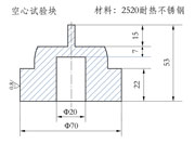

a) Solid specimen b) Sectional view of hollow test block c) Large ring and small ring used as isolation bank
Figure 3 Solid test block a), hollow sample b) and large rings and small rings used as isolation banks
Test cooling medium
A colorless transparent low viscosity base oil was used as the liquid cooling medium for the test. The test oil is contained in a square glass jar. The oil temperature before placing the sample was set at 30 °C. The sample was heated in a small box furnace. Record the cooling process of the sample with a normal camera. The recording speed is 25 sheets per second.
Considering that the upper part of the sample is the portion where the bubble is most discharged, in order to prevent the discharge bubble from interfering with the sharpness of the image, the sample is placed obliquely. The circular plane is approximately 700 degrees from the horizontal plane. The attachment of the large ring is to hang on the bottom of the small cylinder, and the bottom of the ring is placed on the observation surface. Another benefit of placing the specimen tilted is that the weight of the large ring can be used to ensure that it is always attached to the viewing plane. The small ring is placed on the bottom of the small cylinder, and the bottom surface of the small ring is close to the circular plane. Fig. 4 is a photograph showing the manner in which the hollow sample enlargement ring is placed when it is cooled in a liquid medium.
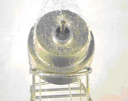
Figure 4 Placement of the hollow specimen when it is hung on the large ring and then cooled in oil
Previous Next
Food Ingredient Transfer Pump,Eggwhite Transfer Pump,Soy Protein Transfer Pump,Yeast Transfer Pump
NINGBO DURREX PUMPS CO.,LTD , https://www.durrexlobepump.com