
introduction
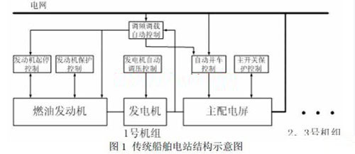
The ship power station is generally composed of a fuel engine, a generator, and a main power distribution panel. As shown in Figure 1, each component has its own input and output signals. The traditional control method is to connect the respective inputs or outputs to the corresponding controller. The control of a single device is realized by the corresponding controller. If the grid detects a large load, a standby generator start signal is automatically generated, and the standby engine controller automatically starts after receiving the signal, delays and establishes a voltage. The generator is controlled by the automatic parallel device to be integrated into the grid. During the operation, the load distribution device automatically adjusts the load. If the grid load is small, the load of each generator is too small after load balancing. The system will automatically unload an original standby generator, and automatically turn off the power and return to the standby state after the delay of the grid operation, to realize the automatic disconnection of the power station.
1. CAN bus and ship power station
With the development of shipping industry and the requirements of ship power stations, bus technology is gradually used in ship control technology, and distributed systems have gradually become the protagonists in the new design system. The Controller Area Network (CAN) module is a serial interface that can be used to communicate with other peripherals or microcontrollers. This interface/protocol is designed to allow communication in noisy environments. Based on the CAN bus and combined with the single-chip microcomputer (MCU) technology, this paper realizes the automatic control of the power supply system consisting of three engines, three generators and three main power distribution panels in the ship power station. monitor.
CAN has several important features: First, the bus protocol is completely open, and the relevant control words and registers can be directly obtained from the relevant CAN chip or MCU. As long as the relevant registers are effectively set, the CAN bus module can automatically communicate. The MCU can directly process the CAN communication information by reading or writing; the second is that the CAN is the underlying protocol, and the user can completely carry out the user-customized high-level protocol on the basis; the third is that the bus has mature market use and reliable resistance. Interference characteristics. Therefore, the CAN bus is also increasingly used in ship control systems.
The ship power station can be divided into the following parts according to the control function:
1) Engine start and stop control 2) Generator voltage control and reactive power distribution control 3) Generator signal detection and protection control 4) Generator automatic parallel control 5) Generator power management control
Each of the above controls has a corresponding sensor, and the signal transmitter and the execution controller are matched with each other. The system implements each link or component with a single-chip microcomputer with a CAN bus. The system structure is as shown in FIG. 2, and the system is divided into For the third floor, the upper layer is a power management controller (PMU) of the power grid, which detects the power usage of the power grid, and sends a start or stop signal to the corresponding controller in the middle layer according to the situation, or sends a load increase and decrease signal. The middle layer is the controller required by each generator. Adjust the control of each power signal, such as voltage or current, as needed. The lower layer is the sensor and actuator layer, and one or several sensors or actuators. All the components that constitute a CAN bus are hung on a CAN bus network. In order to ensure the reliability of the system, each unit in the physical unit has a dual CAN interface. The whole network constitutes two CAN networks, that is, the CAN bus realizes redundant control. On the control of any controller or actuator, any controller can realize redundant control of the controller. In fact, three generators are correspondingly Can be made mutually redundant controller, the redundant controller is not different properties, but the higher level controller Yun (PMU) and with the intermediate function in all controllers, redundant control may be achieved down.

The digital input transmitter 1 detects some basic signals of the fuel engine and converts them into CAN bus interface signals. These basic signals include: cooling water pressure, oil temperature, oil sump oil level, engine standby state, engine automatic Control position, fuel pressure, starting air pressure, etc.; CAN bus 2 is the network bus of the whole system communication, shown as a bus, in order to ensure the system is reliable, using two bus modes, each unit has two bus interfaces, Double bus redundancy is realized; the start and stop output actuator 3 is a relay output with a CAN interface to control the start, stop and emergency stop solenoid valves of the engine; the engine start stop and protection controller 4 is a control core for controlling the engine to run or stop. On the one hand, accept the control button and other signals, on the one hand accept the CAN bus signal, and according to these command signals to control the engine; add and subtract output actuator 5 is a CAN output relay controller with local manual output, its role Is to control the input of the governor inside the engine, to adjust the speed or load; fuel The engine 6 controls the operation according to the start or stop solenoid valve, and adjusts the running speed or output power according to the governor; the analog input transducer 7 such as the rotational speed detects the engine speed, the cooling water temperature, the lubricating oil pressure, the exhaust temperature, and the like. The sensor of important parameters converts the signal into the signal of the CAN bus interface; the power management controller 8 of the power station is the dispatch control unit of the entire control system, detecting the state of the power grid and each engine, realizing automatic control of frequency modulation and load transfer, or realizing automatic Start, or control the automatic unloading and unloading; the pressure regulating actuator 9 is a phase compound excitation automatic voltage regulator controller with CAN bus control, and adjusts its bypass thyristor according to the command from the CAN bus or its own adjustment knob signal. The firing angle is controlled to realize the pressure regulation control of the engine; the generator 10 accepts the excitation adjustment of 9, and the prime mover 6 drives the output power to the power distribution device; the automatic voltage regulation and reactive power controller 11 according to the voltage and current signal of the generator, At the same time, it is necessary to judge the reactive power and power factor values ​​to adjust its output to unit 9 to achieve constant voltage and reactive power distribution equalization; The current signal input transmitter 12 detects the voltage and current signals output by the generator and the phase difference between the two, and calculates the power value, the reactive power value, the power factor value, etc., which are required to be used, and converts them into numbers. The signal is provided to other required links through the CAN interface; the main switch protection controller 13 mainly realizes the overcurrent, undervoltage and reverse power protection of the generator, and the input signal is provided by the link 12, and the main switch and the power distribution screen status signal are used as Auxiliary signal input, which controls the breaking control of the main switch; input transducers such as on-screen buttons convert all operating signals such as buttons on the power distribution panel into standard CAN interface signals and provide them to the CAN network. The main distribution panel 15 is equipped with a main switch, the relay circuit, and the relevant equipment to install its internal power distribution device; the main switch parallel vehicle controller 16 will detect the difference in power between the generator and the power grid, through adjustment The generator realizes the synchronization of the two and automatically parallels the vehicle; the main switch closing/opening actuator 17 is a relay output link with a CAN interface, which is matched with the main switch Energy storage to achieve the main switch, closing or opening control; the power supply bus 18 is three marine power station generator power grid, electrical devices are all external power supply through the present.
Rectangle Chafing Dish,Rectangle Chafing Dishes,Rectangle Chafing Dish With Spring Legs,Mobile Table Ware
Shaoxing Biaoyi Hardware Products Co., Ltd. , https://www.byeob.com