
The layer conversion function is suitable for the following situations: several engineers have to collaborate on design projects, and may use some of their previous drawings for reference, but the layers of these drawings are set differently. In order to better complete the design collaboration, there are It is necessary to set the layers of all the drawings according to the unified standard. Although this can be done manually, it may be very troublesome. Obviously, the software is not lightweight.
In the command line of Haochen CAD2009, input the laytrans command to call the layer conversion function, as shown in the figure.
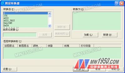
The layer conversion function setting is to change the layer setting of the current drawing to the setting form of other drawings. The layer list on the left is the layer list of the current drawing. You can select the layer to create the layer conversion map. To set which layer these layers are converted to, you need to click the “Load†button on the right side.
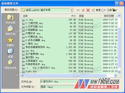
Select the drawing to be converted to. After opening, the layer list of the drawing will appear on the right side of the dialog box.
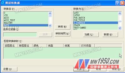
In the list on the left, select the converted layer, select the layer to be converted to in the list on the right, click the "Map" button to create the mapping relationship of the layer conversion, the mapping will be displayed in the list below the dialog box, for all needs to be converted The layers are all mapped together, as shown in the figure.
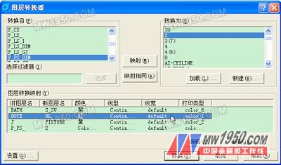
Click the "Convert" button to complete the layer conversion.
* Plate FLANGE (Plate Flange, Flat Flange, Plain Flange)
* SLIP ON FLANGE (SORF SOFF FLANGE)
* WELDING NECK FLANGE (WNRF FLANGE)
* BLANK FLANGE (BLIND FLANGE, BLFF FLANGE, BLRF FLANGE)
* THREADED FLANGE (SCREWED FLANGE)
*BACKING RING FLANGE
Loose Flanges,Stainless Steel Loose Flange,Precision Loose Flanges,DIN 2641 Loose Flange
Shandong Zhongnuo Heavy Industry Co.,Ltd. , https://www.zhongnuoflanges.com